
Selecting Precision Woodworking Tools for Plywood: Accuracy, Tear-Out, and Tool Life
For plywood machining, select the cutting geometry before selecting the nominal diameter. A tool that holds diameter well but fractures the show veneer, packs chips into a deep slot, or loses edge quality after a short run is not a precision tool in production. The preferred choice follows the panel construction, the visible face requirement, the cut type, the machine's hold-down capacity, and the required edge condition before edge banding or finishing.
Start by separating three outcomes that are often grouped together as “cut quality”: dimensional accuracy, veneer integrity, and edge condition. A panel can measure correctly yet show lifted veneer fibers. It can have a clean top face but a rough bottom breakout. It can look acceptable immediately after routing while heat-darkened resin or a worn cutting edge later disrupts edge-banding adhesion. Tool selection should assign a priority to each outcome rather than assume one cutter geometry will optimize all of them.
Read the plywood before choosing the cutter
Plywood is not a uniform routing material. Face veneer species, veneer thickness, adhesive chemistry, core voids, overlapping plies, moisture condition, and surface coatings all influence how a cutting edge behaves. A thin decorative veneer is vulnerable to lifting because the fibers have little support near the surface. A void in the core can allow the cutter to break through suddenly, leaving an irregular internal edge even when the outside veneer appears clean. Dense hardwood faces raise cutting force and heat, while resin-rich panels can deposit material on the flute and imitate the symptoms of a dull edge.
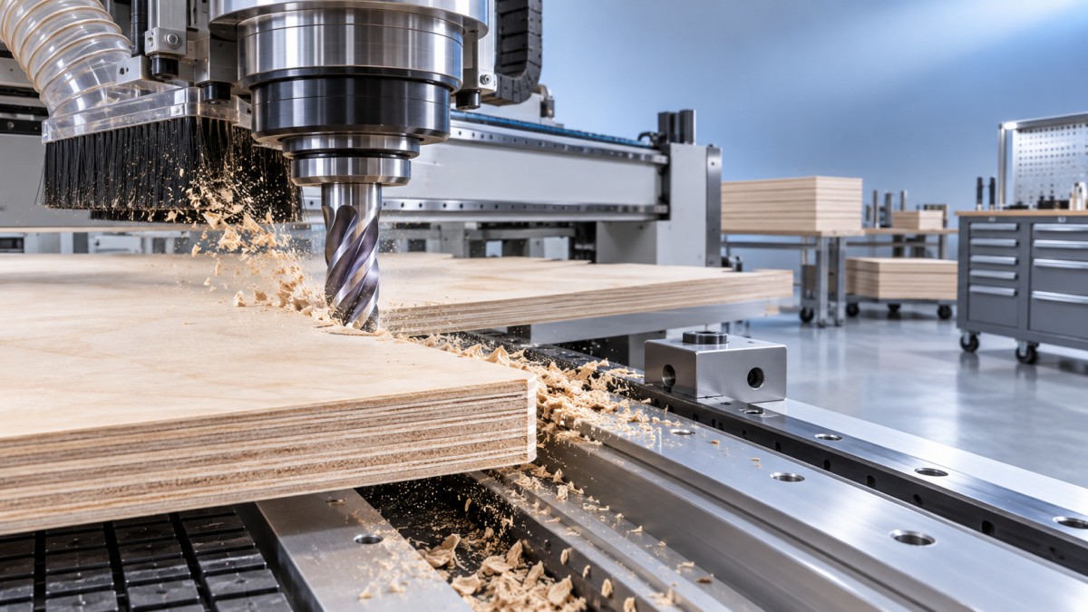
Panel orientation matters as much as panel grade. On a CNC router, the visible face may be on top, bottom, or both. A conventional upcut spiral pulls chips upward and tends to leave a cleaner lower face, but it can lift fibers from the upper veneer. A downcut spiral compresses the upper veneer toward the panel and often improves the top edge, while directing chips into the kerf. Neither is automatically better. The chosen geometry must match which face is exposed and whether the programmed path is a through-cut, a shallow groove, a pocket, or a finishing pass.
When both faces must remain clean on a through-cut, a compression spiral is often the relevant starting point. Its lower section cuts upward and its upper section cuts downward, directing forces toward the panel from both faces. That benefit exists only when the compression transition is correctly positioned relative to material thickness and cutting depth. If the tool enters too shallowly, the wrong portion of the tool engages the top veneer; if it extends too far below the panel, the lower face may still break out. The compression zone is a functional dimension, not a catalog detail.
Match flute geometry to the cut, not just the material name
For drilled holes, shelf-pin bores, hinge cups, and dowel locations, routing cutters should not be treated as universal drilling tools. Brad-point, through-boring, and dedicated drill geometries establish entry location differently and control breakout differently. A router bit used for a hole may produce acceptable diameter in a trial, yet leave a weak entry edge or a torn exit when repeated across varied veneer grain. Hole quality also depends on backing material, spoilboard condition, and whether the tool exits into open air or supported material.
Tool diameter should be chosen from feature radius, required stiffness, and reach. Small diameters allow tight internal corners but deflect more easily in deep cuts. A long-reach cutter magnifies this problem because flute length and projection from the collet reduce stiffness. Increasing diameter can improve rigidity, but only if the machine spindle, collet, nesting layout, and part geometry support it. A larger cutter also changes the minimum internal radius and may remove too much material in narrow channels. Precision begins with a realistic relationship between tool reach and cutting load.
Accuracy is a system result
A nominally accurate tool cannot compensate for collet runout, contaminated tapers, poor tool seating, weak vacuum zones, warped panels, or an unstable spoilboard. Runout causes one cutting edge to remove more material than the others. The overloaded edge dulls first, dimensional variation grows, and the surface may show alternating marks. Because the nominal tool diameter remains unchanged, this problem is sometimes misread as a feed-rate issue.
Measure tool runout close to the cutting length after installation, especially for small-diameter cutters and finish-critical operations. Clean the shank and collet bore before assembly. A damaged or fatigued collet can create intermittent finish problems that appear only after tool changes. Projection should be no longer than the operation requires. Extra projection is often used for convenience, but it increases radial deflection and makes a stable program less stable.
Part movement is another source of false conclusions. A cutter that pulls material upward can weaken vacuum retention around narrow strips or small nested components. The resulting edge wander may be blamed on tool wear even though the cutting edge remains sharp. Tab placement, onion-skin thickness, vacuum zoning, spoilboard permeability, and part sequence all affect the tool's apparent accuracy. When evaluating a new cutter, hold those conditions constant; otherwise, the comparison measures the entire nesting process rather than the cutter.
Chip load, heat, and the false comfort of a smooth edge
Feed rate, spindle speed, flute count, and chip load must be considered together. Raising spindle speed without raising feed reduces chip thickness. At an extreme, the edge rubs instead of shearing effectively, creating heat, resin buildup, premature dulling, and polished or darkened cut walls. A smooth-looking wall is not always evidence of a healthy cut. Heat can seal fine dust to the edge and hide early deterioration until edge banding exposes a weak bond or a visible glue line.
Conversely, forcing an excessive chip load can chip carbide, pull surface fibers, and deflect a slender tool. The right window is constrained by panel density, cutter geometry, tool diameter, spindle power, and the depth and width of engagement. Full-slot cutting has far less room for error than a light finishing pass because the cutter is surrounded by material and must evacuate chips through the same narrow path.
Use the chip stream as evidence. Well-formed chips move away from the kerf. Fine dust, smoking, sharp odor, discoloration, or residue on the flute points toward rubbing, blocked evacuation, unsuitable geometry, or a damaged edge. A downcut tool may require a less aggressive depth strategy than an upcut tool in a deep groove because its chip direction works against easy evacuation. Splitting a deep operation into roughing and finishing can reduce heat and deflection, but only when the finishing allowance is sufficient for the second tool to cut rather than polish the surface.
Carbide grade and coating should solve a defined problem
Solid carbide is widely selected for plywood because it retains a sharp edge under abrasive glue lines and supports rigid small-diameter geometries. However, “carbide” is not a complete specification. Edge preparation, grind consistency, flute polish, carbide grain structure, and brazed versus solid construction affect performance. A very sharp edge may deliver excellent veneer quality but be more vulnerable to micro-chipping in abrasive or contaminated panels. A more robust edge preparation can last longer but may require different cutting conditions to avoid a compressed or fuzzy veneer boundary.
Coatings deserve the same disciplined evaluation. A coating can reduce friction, limit resin adhesion, or improve wear behavior in a particular material and temperature range. It cannot rescue inadequate chip evacuation or compensate for an incorrectly selected cut direction. Coated tools should be assessed against the actual plywood adhesive, surface finish, and production cycle. Some coatings alter edge sharpness or heat transfer characteristics, which can matter more on thin veneer than on the core. Compare like-for-like tools with the same geometry, diameter, projection, and program before assigning value to the coating itself.
For abrasive overlays or film-faced plywood, edge wear may accelerate even when the core routes easily. In these conditions, monitor the finish requirement rather than wait for obvious burning or catastrophic failure. The first indication of wear is often a change in veneer fuzz, a growing burr at the exit face, or a rise in force that affects small-part retention. Tool replacement based only on elapsed machine time misses variation among panel batches and operation types.
Separate tear-out from other edge defects
Tear-out, fuzzing, chipping, and breakout require different corrections. Tear-out usually follows fiber direction and results from insufficient support at the veneer surface or a cutting force that lifts fibers. Fuzzing is commonly associated with a dull edge, rubbing, or unsuitable feed relative to spindle speed. Chipping may indicate a brittle veneer, an impact-damaged cutting edge, excess engagement, or interrupted support over a core void. Breakout on the exit face often points to cut direction, insufficient backing, or compression geometry positioned outside the active cutting zone.
- A clean lower face with a damaged upper face directs attention toward upcut action, top-surface support, or the final segment of a through-cut.
- Burn marks and fine powder in the kerf indicate a thermal and evacuation problem before they indicate a veneer problem.
- Repeated marks at a regular interval around the cut edge suggest runout, damaged flutes, or machine vibration rather than random variation in the plywood.
- An edge that worsens only on narrow parts can reveal hold-down loss or material movement, especially where the cutter's upward force is highest.
Build the evaluation around representative operations
A tool trial should include the real mix of operations: full-depth profile cuts, shallow dados, small-radius corners, drilled features, long grain directions, cross-grain sections, and both visible faces where applicable. Testing only a straight cut in a favorable area of one panel conceals the conditions that consume tools or create rework. Use panels from the intended material range, including the face veneer and core construction that create the greatest quality risk.
Record the installed projection, collet condition, spindle speed, feed rate, step-down, entry method, cut direction, spoilboard state, and vacuum arrangement. Photograph or retain the first acceptable sample and the last acceptable sample from a run. This makes it possible to distinguish gradual tool wear from a setup shift. When a cutter is replaced, inspect the flute under magnification for edge rounding, chipped corners, resin deposits, and localized wear near the compression transition. A tool that fails in one local region often points to an engagement or chip-flow issue rather than a general material limitation.
The best selection is the one that delivers the required tolerance and face quality across the expected panel variation while maintaining predictable service intervals. A cutter with a lower purchase price can cost more when it forces slower feeds, adds hand-cleaning, compromises edge-banding preparation, or causes frequent setup adjustments. Evaluate the finished panel edge, the stability of the process, and the condition of the cutting edge together; plywood routing rewards that combined view.
Related News
Get weekly intelligence in your inbox.
No noise. No sponsored content. Pure intelligence.
