
How to Specify Automated CNC Equipment for High-Mix Custom Furniture Production
High-mix custom furniture production fails when CNC equipment is specified as a cutting machine rather than as a data-to-part system. A machine can have adequate spindle power, a large vacuum table, and an automatic loading device yet still create bottlenecks if it cannot process frequent design changes, preserve part identity, handle variable panel formats, or send reliable machining status back to the production system.
The central specification question is not “What is the fastest CNC router?” It is: What equipment architecture can convert the expected order mix into traceable, correctly machined parts with the least manual interpretation? For custom cabinets, wardrobes, vanities, and built-in furniture, the answer depends on order volatility, part geometry, material mix, downstream edge-banding requirements, and the maturity of the factory’s CAD/CAM and production-control data.
Start with the order profile, not the machine brochure
A high-mix operation should define its manufacturing demand in terms that can be tested against equipment capability. Average board volume alone is insufficient. The technical specification needs a representative order profile showing the range of panel dimensions, thicknesses, materials, machining patterns, nesting density, and rework-sensitive features.
Useful inputs include the smallest and largest processable panels, the percentage of narrow parts, the frequency of one-off components, the share of drilled versus routed features, and the proportion of parts requiring operations on multiple faces. Also separate standard carcass components from visually critical doors, gables, curved parts, slatted elements, and panels with concealed hardware. These groups do not impose the same requirements on clamping, tool access, accuracy, or material handling.
A factory producing mostly rectangular cabinet components may obtain high flexibility from a nested-based router with automatic loading, labeling, unloading, and a capable drilling block. A factory with a large volume of drilled, shaped, or multi-face parts may need a point-to-point machining center, a pod-and-rail configuration, or a coordinated cell rather than attempting to force every part through a nesting machine.
Specification should therefore begin with a part-family matrix. For each part family, identify required operations, datum surfaces, tool types, acceptable edge breakout, need for flip operations, and downstream destination. This turns a generic request for automatic CNC furniture manufacturing equipment into a process definition that suppliers can respond to meaningfully.
Choose machine architecture around process flow
Nesting routers, point-to-point machines, and five-axis CNC centers solve different production problems. They should not be compared only by feed speed or spindle count.
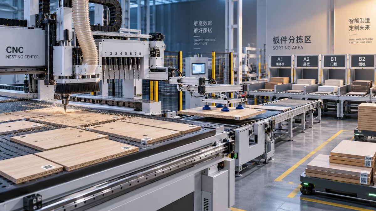
Nesting CNC routers are designed to cut many components from full sheets. Their value lies in material utilization, reduced manual panel sizing, and direct conversion of nested production files into finished blanks. They are especially suitable where panel shapes vary from order to order and where production includes many cabinet parts with drilling, grooving, routing, and contour cutting in a single setup. Their limitations become visible when very small parts lose vacuum holding stability, when through-cuts leave insufficient support, or when the drilling pattern is so dense that routing-based drilling becomes the cycle-time constraint.
Point-to-point machining centers generally provide stronger support for precision drilling, doweling, connector insertion patterns, and machining on positioned workpieces. They can reduce unnecessary routing for repeated hole patterns and may handle narrow components more reliably, depending on the clamp and rail design. Their productivity depends on upstream cutting and part logistics; they do not automatically replace the nesting function.
Five-axis capability is justified when the order mix contains angled drilling, compound contours, shaped doors, solid-wood features, or components requiring tool access from changing orientations. It should not be specified simply as an upgrade. Five-axis heads add programming, collision-control, tool-length management, and maintenance requirements. If nearly all components are flat panel parts with vertical drilling and edge profiles, a well-configured three-axis nesting cell can be operationally more appropriate.
Machine selection should examine where queues currently form. If cutting is slow, adding more drilling capacity will not solve the constraint. If workers spend time sorting, identifying, and moving cut panels, a higher-speed spindle will produce more unmanaged work-in-progress. The preferred architecture is the one that removes the real limiting operation while preserving a coherent flow to edging, sorting, assembly, and packing.
Spindle, drilling, and tooling specifications must reflect real features
Spindle power matters, but it is only one element of cutting performance. Tool diameter, cutter geometry, material density, chip evacuation, hold-down strength, acceleration, and programmed feed rates determine whether the machine can consistently achieve the required finish. A high-power spindle cannot compensate for poor vacuum zoning or inadequate dust extraction when machining melamine-faced particleboard, MDF, plywood, compact laminate, or veneered panels.
Technical specifications should define the operations that must be completed within the target cycle rather than requesting a nominal spindle rating. For example, requirements may include through-cut nesting of coated board, blind-hole drilling for hinges and connectors, dadoes, back-panel grooves, routed pulls, and contouring of shaped panels. The supplier should identify which operations use aggregate heads, vertical spindles, horizontal drills, or the main routing spindle, and state the implications for cycle time and tool changes.
The drilling block deserves particular scrutiny. Custom furniture frequently relies on repeatable hole geometry for hinges, shelf pins, dowels, cam fittings, confirmat screws, and concealed connectors. Verify vertical and horizontal drilling configuration, minimum usable workpiece width, drill spacing, aggregate availability, and the machine’s ability to complete drilling close to edges without compromising holding. If horizontal machining requires a flip, that flip must be modeled as part of the cell cycle, not treated as an operator detail.
Automatic tool changing should be sized for the actual tool library and expected variation, including backup tools for high-wear cutters. Tool holders, collets, length measurement, breakage detection, and tool-life monitoring are often more consequential than a nominally large carousel. A machine that stops because an operator must identify and replace a worn compression cutter is not functioning as an automated cell.
Vacuum zoning and material handling determine usable automation
For panel processing, the vacuum system is a production-control component. Its performance depends on pump capacity, leakage management, spoilboard condition, zone design, gasketing strategy, and the nesting pattern. The specification should state the smallest expected part size, the frequency of narrow strips, and whether onion-skin machining, tabs, bridges, or routing strategies are acceptable. These choices affect both finish quality and the risk of part movement during final cutout.
Automatic loading and unloading should be assessed as a sequence, not as separate options. Loading must correctly identify material, thickness, face orientation, and sheet condition. Unloading must deal with cut parts, offcuts, and waste without mixing orders or damaging finished faces. A cell that handles only intact full sheets but requires manual intervention for remnant sheets, bowed panels, protective films, or small parts may be appropriate, but those limitations need to be explicit in capacity planning.
Barcode or QR-based identification is particularly important in high-mix manufacturing. The identifier should be assigned early enough that each part can retain its order, cabinet, room, material, and revision status through machining. Labels need to be readable after dust exposure and positioned so they do not interfere with edge-banding or visible surfaces. The system should also define what happens when a label fails to print, scans incorrectly, or belongs to an obsolete revision. These are ordinary exception states, not rare events.
Software integration is the real flexibility layer
Custom production begins in design software, but machining reliability depends on how design intent is translated into manufacturable data. The CNC supplier’s post-processor, CAM environment, optimization engine, labeling system, and production interface should be assessed together. Manual file repair may appear manageable at low volume, but it becomes a hidden quality risk when every order has a different configuration.
The required data flow should be mapped from design approval to shop-floor execution. At a minimum, the system needs controlled transfer of panel dimensions, material code, grain direction, visible faces, machining rules, hardware information, edge-banding requirements, and revision identifiers. A change to a cabinet width or hinge type should trigger a controlled update rather than leaving an older CNC program available at the machine.
MES connectivity is valuable only when the interface supports operational decisions. Useful functions include release of approved jobs, real-time machine state, completion confirmation, rejected-part reporting, tool alarms, and traceability by job or batch. The interface method, data ownership, version control, and fault behavior should be defined before purchase. A promised “MES-ready” capability is not a specification. Require clarity on supported protocols or APIs, required middleware, responsibilities for integration, and the information that can actually be exchanged.
Optimization software also needs constraints beyond sheet yield. It must respect grain direction, finish orientation, panel defects where relevant, edge-band allowances, tool paths, hold-down islands, and downstream sorting needs. A mathematically efficient nest can be operationally poor if it produces many fragile parts, overloads a single edging pattern, or mixes components from too many orders on one unloading table.
Define accuracy in relation to assembly, not as a headline number
Machine positioning accuracy is not the same as finished furniture accuracy. The assembled result is influenced by board movement, tool runout, cutter wear, vacuum stability, datum logic, programming conventions, temperature, and material behavior. A specification should define critical features and how they will be measured: hole-to-edge position, opposing-hole alignment, groove position, squareness, panel length and width, routed profile consistency, and edge quality.
It is equally important to identify the datum convention. If drilling coordinates reference an edge that will later be trimmed, edged, or processed differently, nominally accurate machining can produce poor assembly alignment. The equipment supplier, software provider, and furniture engineering team need a common rule for reference faces, finished dimensions, and compensation values.
Acceptance criteria should use representative production parts rather than only a simple calibration panel. The test set should include coated board, MDF or plywood where applicable, narrow components, dense drilling patterns, large panels, and parts that require critical assembly relationships. Evaluation should cover cycle repeatability, dimensional conformity, chip-out, label accuracy, part sorting, and recovery after a planned interruption. A machine can pass a dry run while still failing the order mix it was purchased to process.
Do not isolate CNC selection from edging and dust control
CNC machining quality is often judged at the edge bander and during assembly. Router tear-out, inconsistent panel dimensions, incorrect grain orientation, and poorly labeled parts create downstream defects that may be incorrectly attributed to edging or installation. The selected machine should generate cut edges compatible with the intended edge-banding process, whether EVA, PUR, laser, or another technology is used. This includes consideration of chip-out on decorative faces, corner quality, and the dimensional allowances used by the edging program.
Dust extraction requires the same level of engineering attention. Insufficient airflow can impair cut quality, obscure sensors, increase cleanup, and create fire and health risks depending on material and local requirements. The CNC specification should define connection dimensions, expected extraction demand, filtration responsibilities, waste separation, and whether the existing extraction plant can support simultaneous operation with loaders, edge banders, and other woodworking equipment. Material types matter: MDF, particleboard, plywood, solid wood, and composite panels do not generate identical chip behavior.
Specify exceptions and maintainability before commissioning
High-mix automation is tested by exceptions: a damaged board, a changed design revision, a missing tool, a vacuum alarm, an unreadable label, an interrupted nest, or an urgent remake part. The equipment and software should provide clear alarm states, safe restart procedures, job recovery logic, and traceable records of what was completed. Uncontrolled restarting can create duplicate parts or, worse, partially machined components that appear complete.
Maintenance access should be evaluated in the proposed factory layout. Check clearance for pumps, electrical cabinets, tool magazines, automatic loaders, lubrication points, spoilboard resurfacing, and dust ducting. Ask for the recommended preventive-maintenance schedule, consumables list, remote-support conditions, spare-part lead-time arrangements, and software update policy. The availability of local service capability may affect the practical value of a sophisticated machine more than an incremental performance advantage.
The strongest specification is therefore an operational contract between furniture engineering, software, material handling, machining, and downstream assembly. It defines the parts to be made, the data that controls them, the exceptions that must be recoverable, and the measurable output condition. When those elements are clear, automated CNC equipment can support customization without turning every new order into a manual programming and sorting exercise.
Related News
Get weekly intelligence in your inbox.
No noise. No sponsored content. Pure intelligence.
