
CNC Cutting and Drilling for Wardrobes: A Panel Processing Guide
Accurate wood cutting and drilling for wardrobes starts with more than loading a panel and pressing start. Operators must account for material thickness, tool selection, workholding, and hole positioning to produce components that fit together reliably.
This guide walks through the CNC panel processing workflow, from preparing cutting files to checking finished parts. Whether you are making standard cabinets or customized wardrobes, these practical steps can help reduce errors, improve consistency, and keep production moving efficiently.
What Determines Whether Wardrobe Panels Fit?
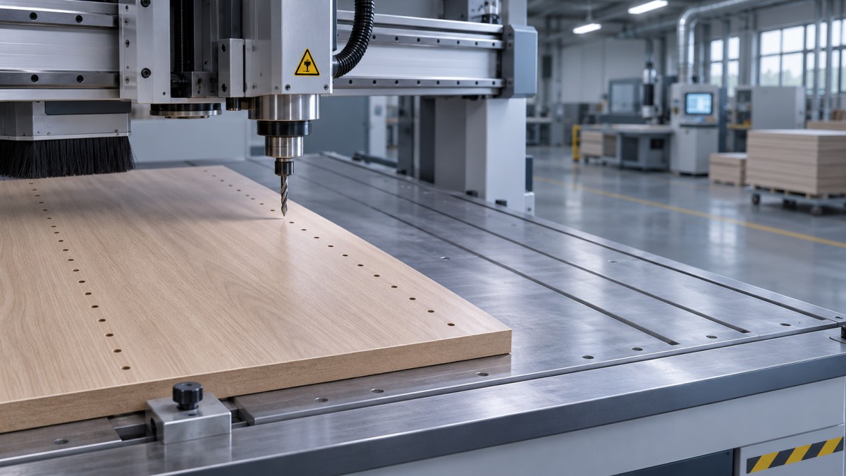
The most reliable results come from controlling three linked factors: the actual panel dimensions, the relationship between machined features, and the reference edges used throughout production.
A clean cut alone is not enough. A side panel can be square and attractive yet still fail assembly if hinge holes or shelf-pin rows are referenced incorrectly.
Before running a full batch, confirm the material thickness, panel orientation, edge-banding allowances, and hardware drilling pattern. Then machine and assemble a representative test piece.
For custom wardrobes, pay particular attention to mirrored left and right panels. They may share dimensions but require holes on opposite faces or edges.
1. Check the Material Before Programming
Wardrobe components commonly use melamine-faced particleboard, medium-density fiberboard, plywood, or veneered panels. Each material behaves differently during cutting, drilling, and edge finishing.
Melamine surfaces can chip as a tool enters or exits. Particleboard edges need careful support, while plywood may show tear-out where veneer grain changes direction.
Measure thickness at several points with a caliper, especially when a new batch arrives. Use those measurements to verify groove depths, connector engagement, and assembly clearances.
Check sheets for bowing, damaged corners, loose surfaces, and inconsistent dimensions. Mark defects before nesting so visible parts are not placed over damaged areas.
Also identify the decorative face and grain direction. A panel that fits mechanically can still be rejected if its grain runs against adjacent doors or drawer fronts.
2. Prepare a Cutting File That Matches the Assembly
Start with an approved design and a current cutting list. Include finished dimensions, material thickness, quantities, grain direction, edge-banding requirements, and component identification.
Separate finished dimensions from CNC cutting dimensions. If an edge will receive banding, calculate the required pre-banding size using the specified band thickness and shop convention.
For example, a panel requiring a 600 mm finished width with 1 mm banding on both opposing edges would typically be cut to 598 mm.
Confirm that the drawing dimensions refer to the finished component and account for any subsequent trimming. Measure a banded sample when the required fit is tight.
Assign every part a clear label, including its job number, orientation, and visible face. Labels help prevent a correctly machined panel from being installed in the wrong position.
Before exporting toolpaths, check for duplicate geometry, open contours, overlapping cuts, and features outside the panel boundary. Simulate the program using the correct sheet size.
3. Set a Consistent Reference and Check Hole Positions
Choose the machine datum and panel reference edges according to the machine setup and program. The physical sheet position must match the origin used in the file.
Confirm which face is upward during machining. If a panel must be flipped, define a repeatable locating method and verify how the second setup transforms the coordinates.
Hardware manufacturers provide the controlling dimensions for hinges, drawer slides, connectors, and shelf supports. Use the exact product specification rather than assuming every fitting shares a pattern.
For example, a concealed hinge may use a 35 mm cup, but cup depth, edge distance, and fixing-hole positions vary by hinge and door application.
Shelf-pin holes are often arranged on a 32 mm pitch, but their distance from the panel edge and their usable range depend on the cabinet design.
Check hole diameter, depth, spacing, and distance from the reference edge. A depth stop in the program does not compensate for an incorrect tool-length measurement.
For mirrored components, inspect the face, edge reference, and hardware positions on both versions. A test assembly is often faster than correcting an entire batch.
4. Choose and Inspect Cutting and Drilling Tools
Select tools for the panel material, required finish, machine capability, and production volume. Confirm that the tool diameter and cutting length match the programmed operation.
For laminated panels, an appropriate compression cutter can improve top and bottom edge quality when the cutting depth engages the tool geometry as intended.
Compression tools are not a universal solution. On shallow passes, the required cutting section may not engage correctly, so confirm the tool manufacturer’s recommended application.
Use boring bits suited to the hole type and material. A clean blind hole needs an appropriate bit geometry, accurate depth control, and effective chip removal.
Inspect cutting edges, collets, tool holders, and drill bits before production. Chipped or dull tools can cause tear-out, overheating, oversized holes, and inconsistent edge quality.
Clean the collet and tool shank before installation, and follow the machine and tooling manufacturer’s clamping instructions. Replace damaged components instead of compensating through feed adjustments.
5. Secure the Sheet and Verify the Setup
Vacuum tables are common for nested panel processing, but holding performance depends on the spoilboard, vacuum zones, sheet condition, seal quality, and available vacuum capacity.
Cover unused table areas where the machine setup requires it. Check the spoilboard for excessive wear or leakage, and confirm that the sheet sits flat.
Small parts are especially vulnerable to movement near the end of a cut. Use an approved strategy such as tabs, an onion-skin pass, or suitable mechanical holding.
Each strategy has trade-offs. Tabs and onion skin can improve retention but introduce additional cleanup or a final pass, so validate the resulting edge quality.
Before cutting, verify the correct program, material, sheet orientation, tool numbers, tool offsets, and machine origin. Confirm extraction and safety devices are operating as required.
Run a simulation or dry run when appropriate, following site procedures. Keep hands clear of moving equipment and never bypass guards or reach into an active machine.
6. Cut and Drill a Test Panel Before the Batch
For a new material, tool, hardware set, or program, start with a representative test. Include critical holes, a finished edge, and any groove or connector feature.
Set spindle speed, feed rate, and drilling parameters within the ranges recommended by the tool and machine suppliers. Adjust only after observing the actual result.
Listen for unusual vibration and check for burning, dust buildup, or poor chip evacuation. Stop the machine safely before inspecting or measuring any part.
Excessive rubbing can generate heat and shorten tool life, while an overly aggressive feed can damage edges or overload the tool. Both require investigation.
Check the first panel against the drawing, then test the actual hardware where practical. Record the approved settings and any changes for the remaining batch.
7. Inspect Parts Before Edge Banding and Assembly
Measure overall length and width, then compare diagonal measurements as a practical squareness check. Investigate unexpected differences against the drawing and the shop’s acceptance tolerances.
Inspect both faces and all machined edges for chips, breakout, burn marks, and movement marks. Separate defects that banding will cover from damage affecting visible surfaces.
Use calipers, a depth gauge, or an approved checking fixture to verify critical holes and grooves. Check the location from the same reference edges used in programming.
Confirm that blind holes do not break through the opposite face and that fittings seat correctly. Check a sample of repeated features throughout the run.
After banding, verify finished dimensions and edge quality again. Edge banding protects and finishes exposed edges, but it does not make a panel completely waterproof or eliminate emissions.
Common Problems and What to Check First
Chipped laminate: Inspect tool condition and cutting direction, then confirm the selected tool and pass depth suit the material. Check sheet support and extraction.
Parts move during cutting: Check vacuum zones, spoilboard leakage, sheet flatness, and small-part holding. Review the cutting sequence and retention strategy before restarting.
Holes are misaligned: Verify the datum, panel orientation, tool offsets, and hardware drawing. Compare left and right parts to catch incorrect mirroring.
Hole depth varies: Measure actual panel thickness and check tool length, table condition, and sheet seating. Inspect for debris preventing the panel from lying flat.
Finished panels are the wrong size: Check tool diameter compensation, programmed dimensions, and edge-banding allowances. Measure a test component before changing multiple settings.
Change one suspected cause at a time where practical, then rerun a controlled test. Record the outcome so the correction can be repeated on future jobs.
Final Checklist for Reliable Wardrobe Production
Successful wood cutting and drilling for wardrobes depends on a verified chain from design to assembly: accurate dimensions, correct references, secure holding, suitable tooling, and inspection.
Before releasing a batch, confirm the first panel fits its intended hardware and matches its finished-size requirements. Repeat checks when materials, tools, or machine conditions change.
For customized work, give mirrored panels and face orientation the same attention as cut quality. These checks prevent costly rework even when the machine runs accurately.
Related News
Get weekly intelligence in your inbox.
No noise. No sponsored content. Pure intelligence.
