
Choosing Panel Furniture Equipment for Wardrobes: Capacity and Workflow
Selecting panel furniture production equipment for wardrobes requires more than comparing machine speeds. A line that cuts panels quickly can still struggle to deliver finished components if edge banding, drilling or sorting cannot keep pace. For technical evaluators, the challenge is to match capacity to order volume, panel dimensions and product variation while accounting for material handling, software integration and quality requirements.
The best starting point is not a machine catalogue. It is a representative wardrobe order: how many different parts it contains, which edges are visible, what hardware it uses and how those parts must move through the factory. From there, equipment specifications become easier to interpret—and harder to mistake for production capacity.
Start with the wardrobe, not the machine
Wardrobes may share a basic construction, but their manufacturing requirements vary. A standard carcass with repeated shelves behaves differently from a made-to-measure installation with tall side panels, drawers, angled components and customer-specific hardware. Those differences influence nesting efficiency, edge-banding passes and drilling time.
Build a production profile using actual or forecast orders. Include a typical order, a high-volume order and a difficult custom order. For each, record:
- Finished part quantities, dimensions, thicknesses and material types.
- The proportion of repeated parts versus unique parts.
- Edge material, thickness and the number of edges to be banded.
- Drilling, grooving and routing operations, including work on multiple faces.
- Hardware requirements and any tolerances critical to assembly.
- Daily or weekly demand, delivery deadlines and expected order variation.
Large wardrobe sides deserve particular attention. A machine may accommodate the raw sheet but still need adequate support for long finished panels during transfer, banding and drilling. Check both minimum and maximum part sizes: narrow drawer components can be just as restrictive as oversized doors.
Translate demand into capacity at each workstation
Published feed rates are useful for comparing machines, but they do not describe a complete shift. A capacity estimate should include loading, unloading, tool changes, program calls, labeling, cleaning, maintenance and ordinary interruptions. Use the same assumptions when comparing alternatives.
Begin with available production time per shift, then deduct planned breaks and downtime. Divide that net time by a realistic cycle time for the representative part mix. Repeat the calculation for cutting, edge banding and drilling rather than assuming that one machine’s output determines the whole line.
For example, suppose the available time for each workstation is 420 minutes per shift after planned stoppages. A cutting process averaging 1.4 minutes per finished component would have a theoretical capacity of 300 components per shift under those assumptions. If downstream drilling averages 1.75 minutes per component, its corresponding capacity is 240. The line cannot sustainably finish 300 components without additional drilling capacity, overtime or a change in the work mix.
This is an illustrative comparison, not a machine benchmark. The calculation must also account for the fact that not every component receives the same operations. A panel requiring drilling on two faces consumes different capacity from an undrilled filler strip; a door may need four banded edges while an internal part needs only one.
Useful capacity measures differ by process: assess cutting in sheets and finished parts, edge banding in processed edges or edge length, and drilling in parts and machining time by operation. Convert them back to the same representative order before deciding where the constraint lies.
Follow the panel through the workflow
A practical wardrobe production route may look like this:
Design and order data → sheet preparation → cutting and labeling → edge banding → drilling and routing → inspection → order sorting and packing.
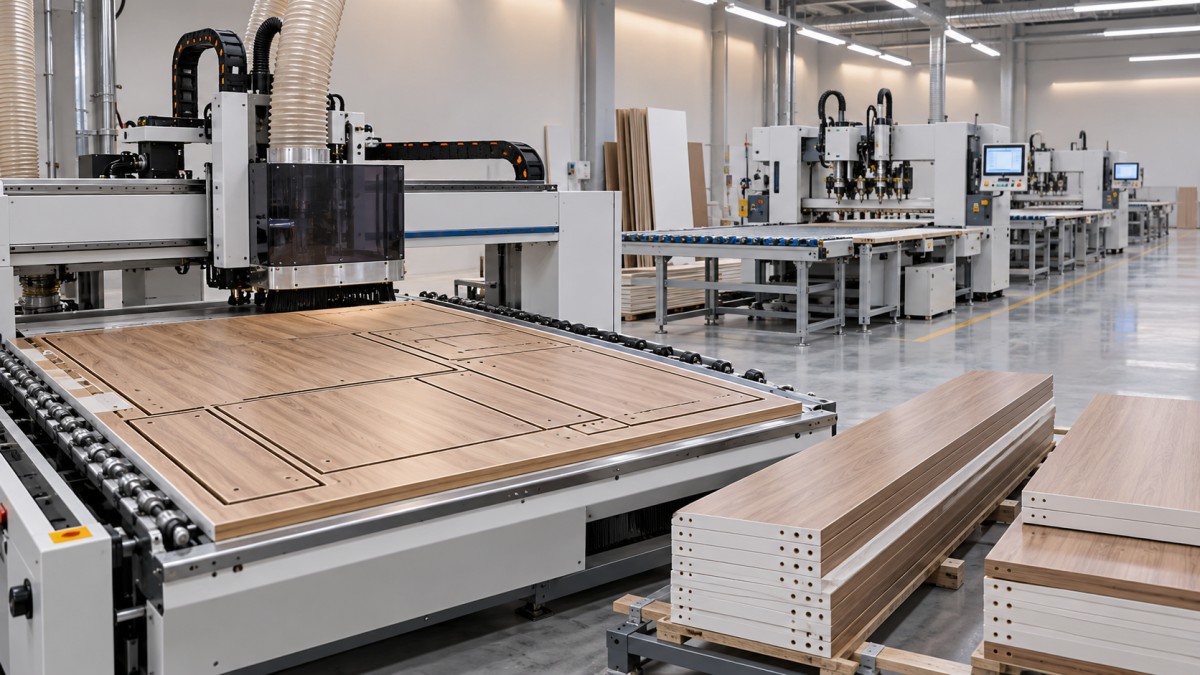
The exact sequence depends on the product and equipment. Some nesting CNC routers can perform selected drilling operations during cutting; other holes or hardware details may be better handled after banding on a dedicated drilling machine. Map the real sequence for each part family, including any return trips to an earlier workstation.
At each transfer, ask how the part is identified, who moves it and where it waits. A fast machine feeding an unorganized stack can create a hidden queue. Mixed orders may then require manual searching, increasing handling damage and making a late component difficult to trace. Conveyors, return systems or automated loading may help, but only if the layout and order mix justify them.
Allow space for incoming sheets, work in progress, finished-part carts and maintenance access. Also check doorways, turning radii and safe handling of large panels. A layout that fits on a drawing is not necessarily one that operators can run comfortably with a full day’s production around them.
Compare the main equipment choices against the workload
Cutting: nesting CNC router or panel saw?
A nesting CNC router is often attractive when wardrobe parts vary from order to order. It can cut shapes, create grooves and perform some drilling from digital programs, reducing separate handling for suitable components. Evaluate the usable bed size, vacuum holding zones, tool capacity, dust extraction and the time needed to load and unload sheets. Small nested parts require particular attention: insufficient hold-down or an unsuitable cutting strategy can affect accuracy and safety.
A beam saw or panel saw may suit production dominated by rectangular parts and repeated cutting patterns. Its value depends on factors such as batch size, pattern complexity, material handling and downstream sorting. Compare both approaches using the same orders; nesting utilization alone is not enough if machining time or part collection becomes the limiting factor.
Edge banding: measure the job beyond feed speed
For wardrobes, edge appearance is visible every time a door opens. Assess the machine’s ability to apply the required band materials and thicknesses consistently, as well as its trimming, scraping and finishing units. Confirm the minimum distance between parts, changeover requirements and performance on both long panels and small components.
Adhesive selection affects the process as well as the finished joint. PUR and other hot-melt systems have different operating, cleaning and maintenance requirements; match the choice to the material, end-use environment and supplier instructions. Edge banding can improve the appearance and durability of exposed edges, but it should not be treated as a guarantee of waterproofing or the elimination of emissions. Board specification, adhesive, application quality and testing all matter.
Drilling and routing: protect assembly accuracy
Hinge cups, shelf-pin rows, drawer slides and connector holes must align with the chosen hardware system. Check spindle configurations, working faces, positioning methods and the machine’s ability to process the full range of part dimensions. For a flexible wardrobe line, setup time and program changeover may matter as much as the fastest drilling cycle.
Ask how the machine handles reference edges after banding and how it compensates, where applicable, for edge thickness. A small mismatch between design assumptions and machining references can appear later as an assembly problem rather than an obvious machine fault.
Make software integration part of the equipment evaluation
Wardrobe customization places unusual pressure on data. A revised width can change the cutting pattern, hole positions, edge instructions and packing list at once. If those changes are copied manually between systems, the shop floor may receive a mixture of old and new information.
Trace a sample order from design through production. Establish whether the design or production software can generate the required machine programs, labels and part lists, and identify any conversion or operator input between stages. Confirm file formats, post-processors, network requirements and responsibility for maintaining the connection when either system is updated.
Labels or barcodes should identify the part and order clearly enough for downstream processing and sorting. Where production tracking or MES integration is planned, define what information must be exchanged: machine status, completed operations, rejected parts or order progress, for example. Do not assume that a network port automatically provides the data or integration needed.
Request a production trial that exposes the constraints
A demonstration using one easy panel can show that a machine runs; it cannot establish whether the proposed workflow meets demand. Provide prospective suppliers with representative materials, edge bands, part drawings and machining requirements. Include long sides, small parts, common hardware patterns and at least one awkward custom order.
During the trial, record elapsed time and distinguish automatic machining from loading, unloading, changeovers and inspection. Count operators and note where parts accumulate. Verify dimensions, squareness, edge quality, hole position and assembly fit against agreed tolerances. If possible, repeat the test with a mixed batch rather than a single optimized part.
Ask suppliers to state the assumptions behind their capacity estimates, including part mix, staffing and utilization. Clarify which items are included in the quotation: tooling, extraction, material handling, software interfaces, installation, training and commissioning can all affect the comparison. Check service access, spare-parts availability and preventive maintenance requirements alongside the machine specification.
Choose for the constraint you expect to manage
The strongest equipment choice is rarely the one with the highest headline output. It is the configuration that can complete the required mix of wardrobe orders, at the required quality, without pushing an unmanageable queue into the next operation.
Before approving an investment, compare expected demand with demonstrated station capacity, confirm that the proposed data flow works, and leave a plan for growth. That may mean adding handling before buying another machine, reserving space for a second drilling station, or choosing a more flexible setup over maximum speed. PWFS follows developments in CNC woodworking and panel-processing systems; the same principle applies across the field: evaluate the connected production workflow, not isolated specifications.
Related News
Get weekly intelligence in your inbox.
No noise. No sponsored content. Pure intelligence.