
Precision Woodworking: How CNC Accuracy, Tooling, and Fixturing Affect Part Quality
Precision Woodworking: How CNC Accuracy, Tooling, and Fixturing Affect Part Quality
Precision woodworking is often discussed as if it were a specification on a CNC router: positioning accuracy, repeatability, spindle speed, or the number of controlled axes. Those figures matter, but they do not decide part quality by themselves. In production, the finished panel is the result of a chain: CAD data, nesting strategy, machine motion, tool geometry, vacuum holding, board condition, chip extraction, and downstream edge treatment. A machine can be mechanically capable of fine positioning and still produce inconsistent parts if one of those links is unstable.
For custom furniture, cabinet, door, and interior-fitout operations, the practical question is not whether a router can cut a panel once. It is whether it can repeatedly create parts that assemble without force, accept edge banding cleanly, keep drilling patterns aligned, and remain predictable across different board lots and shift conditions. That is the working definition of precision woodworking: controlled variation, not simply high advertised accuracy.
This distinction becomes more important as whole-house customization moves from skilled manual adjustment toward digital production. A front-end design system may generate thousands of unique components, yet the factory still has to make every shelf, side panel, drawer front, and connection hole fit at the assembly station. The router is central to that process, but it must be evaluated as part of a production system rather than as an isolated machine.
Machine Accuracy Is a Starting Point, Not a Finished-Part Guarantee
Technical evaluations often begin with axis accuracy and repeatability. That is reasonable, but the two terms should not be treated as interchangeable. Accuracy describes how closely an axis reaches its commanded position. Repeatability describes how consistently it returns to that position. In panel processing, repeatability can be the more revealing measure because a production line depends on stable results over many cycles, not one favorable measurement during acceptance testing.
Even then, axis performance is only one contributor. A moving gantry changes behavior under acceleration. A long tool amplifies runout and deflection. A heavy aggregate head has different dynamic demands from a compact drilling block. The machine frame, drive system, spindle condition, servo tuning, and controller’s ability to maintain the programmed path at corners all affect the geometry left on the board.
A common production symptom is a part that measures correctly along a straight cut but shows mismatch at inside corners, tight radii, or repeated pocket features. This may be blamed on the CAM program when the issue is actually a combination of feed rate, axis acceleration, cutter load, and insufficient hold-down near the cut. Conversely, slowing a program excessively may conceal a mechanical or workholding weakness while sacrificing throughput. Good evaluation separates these causes instead of accepting a slow, carefully staged demonstration as proof of real capacity.
It also helps to distinguish machine-coordinate accuracy from process capability. A router may return accurately to its home position while the panel moves slightly under cutting force. From the controller’s perspective nothing is wrong; from the assembler’s perspective the drilling pattern is off. Finished-part verification must therefore include real materials, representative geometries, and normal production tooling.
Thermal movement and calibration discipline
Woodworking environments are not metrology laboratories. Ambient temperature, dust accumulation, lubrication condition, and machine warm-up all influence behavior. The same applies to engineered panels, which may react to moisture exposure and internal stress. Shops that require close mating between routed components should establish a routine for checking tool length offsets, spindle condition, reference points, and spoilboard flatness. Calibration is not a one-time commissioning event.
For a technical evaluator, the useful question is: what is the manufacturer’s procedure for proving and maintaining accuracy after installation? Look for accessible reference features, practical diagnostics, service documentation, and a clear distinction between machine calibration and application validation. A capability claim without a maintenance method has limited value in a high-mix plant.
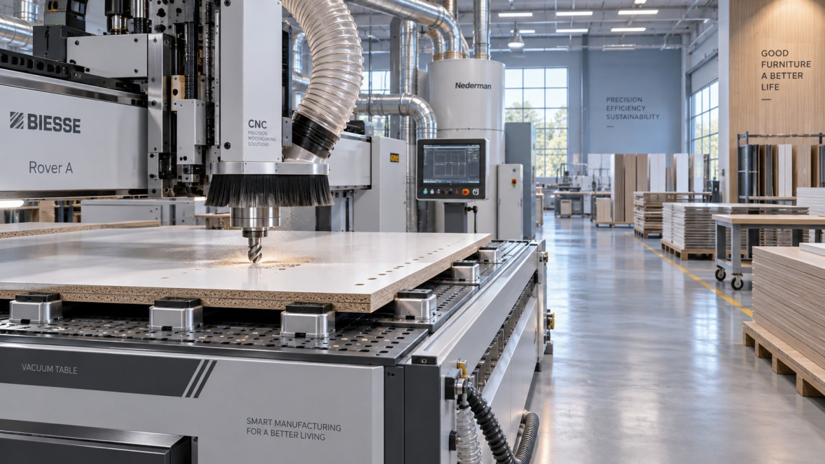
The Cutting Tool Is Part of the Motion System
In precision woodworking, the cutter is not a consumable detail. It is the point where digital geometry becomes a physical edge, and it strongly influences both dimensional result and appearance. Tool diameter, flute configuration, coating, cutting direction, stick-out, and balance all change the process. A nominally correct program cannot compensate for a dull compression bit, excessive runout, or a tool selected for a different panel construction.
Consider laminated particleboard or MDF. The quality requirement is rarely limited to the cut size. Operators also care about chip-free decorative faces, a clean edge for subsequent banding, and minimal fuzzing or breakout at drilled holes. A tool that leaves a rough or fractured edge may force extra cleanup, reduce edge-band adhesion consistency, or expose defects after handling. In furniture plants, that cost often appears downstream, where it is harder to trace back to the router.
Compression spirals are widely used for double-sided laminated panels because their opposing cutting directions can help protect both faces when cutting conditions are appropriate. Yet they are not automatically the best answer. The compression zone must engage the material correctly, and a poor choice of plunge strategy can still damage the top surface. For groove cutting, drilling, or machining solid timber, a different tool geometry may be more suitable. Evaluators should ask which tools are being proposed for which operations, not simply how many tool positions the machine has.
Tool life management deserves similar attention. A cutter can remain intact while no longer producing an acceptable edge. Tool-change intervals should be based on material, operation, quality expectation, and observed wear rather than a generic calendar rule. This is especially relevant where recycled-content panels, abrasive coatings, mineral-filled boards, or high-volume laminated products are processed. These materials can change the wear pattern substantially.
Chip evacuation is not merely housekeeping
Poor extraction can turn a sound cutting recipe into an unstable one. Chips remaining in a narrow slot create heat, are recut by the tool, and can abrade the finished edge. Dust around a vacuum cup can also compromise holding. On nested-based CNC systems, extraction performance has a direct relationship with tool temperature, cut cleanliness, spoilboard condition, and the operator’s ability to inspect the process. It should be reviewed together with spindle power and cutting parameters, not after the machine selection is complete.
Fixturing Determines Whether the Programmed Part Stays Put
Workholding is frequently underestimated because it is less visible than a five-axis head or automatic tool changer. Yet fixturing often determines whether the machine’s theoretical precision reaches the workpiece. Vacuum pods, grid tables, mechanical clamps, reference stops, and custom fixtures each have a place. The right approach depends on panel size, surface condition, machining sequence, part size, and the balance between flexibility and repeatability.
Nested routing on a spoilboard is efficient for high-mix cabinet components, but it creates a familiar challenge: small finished parts lose support as the cut nears completion. If tabs, onion-skin strategies, vacuum zoning, or sequencing are poorly planned, the part may shift in the final pass. The resulting error can be subtle—a slightly oversized slot, a damaged edge, or a component that fails to align during dowel insertion. That is precisely the type of defect that escapes a casual visual inspection but creates assembly friction later.
Pod-and-rail systems can offer more accessible edge machining and allow workpieces to be elevated, but setup discipline becomes critical. Pod locations, seal condition, vacuum availability, and datum referencing must be consistent. A small placement error can be transferred through every hole pattern and contour. For repeat production, dedicated fixtures may seem less flexible, yet they can be the more dependable choice when the cost of variation is high.
Material condition complicates the picture. Panels that are bowed, warped, or dusty may not seal well to a vacuum surface. Solid wood adds grain direction, residual stress, and moisture-related movement. There is no universal holding recipe. A responsible process review includes the least cooperative material that is likely to arrive in normal production, not only flat sample sheets selected for a demonstration.
Programming Strategy Connects Accuracy to Throughput
CAM decisions determine how cutting forces are introduced to the panel. Entry and exit moves, climb or conventional cutting direction, ramping, toolpath order, nesting density, and final-pass strategy all affect the result. A technically accurate router can still produce poor edge quality if the program drives an unsuitable tool too aggressively through a decorative surface.
The best machining strategy is rarely the fastest line in isolation. A route that reduces cycle time but causes edge cleanup, rework, or edge-banding defects is not productive. Equally, a highly conservative program may protect quality but prevent the factory from meeting delivery commitments. The objective is a stable operating window: settings that tolerate ordinary material variation and operator changes without producing a sudden jump in defects.
This is where production data becomes useful. Rather than relying on a single overall machine utilization figure, teams should observe part-level indicators: first-pass acceptance, edge defects, rejected drilling patterns, tool changes, vacuum-related stops, and assembly adjustments. A manufacturing execution system can make these patterns easier to see, but the discipline matters more than the software label. If defects are recorded only as “quality issue,” the factory loses the chance to distinguish tool wear from spoilboard leakage, incorrect nesting, or programming changes.
Judge the Router by the Downstream Operation
A CNC-cut panel is seldom the final product. It may pass to drilling, edge banding, sanding, hardware insertion, spray finishing, or assembly. That is why precision should be assessed at the handoff points. Does the edge provide a stable substrate for the selected adhesive system? Do hardware holes align after the panel has been turned or moved? Does a routed recess remain clean enough for fitting without manual trimming? Can the part be identified and tracked through a mixed-order workflow?
Edge banding is a particularly revealing downstream test. A clean, square routed edge supports a more consistent result, but routing alone does not guarantee bond quality. Adhesive selection, edge-band material, pre-milling, panel storage, machine temperature control, and finishing settings all need to be evaluated together. Laser or PUR-based edge-banding processes may address specific appearance, moisture-resistance, or application requirements, but they do not remove the need for well-controlled upstream machining.
The broader lesson is shared across industrial print, packaging conversion, and panel furniture manufacturing. High-speed systems only become dependable when registration, material handling, cutting forces, and inspection remain connected. PWFS tracks these adjacent equipment disciplines because a folding carton’s die-cut registration problem and a cabinet panel’s drilling mismatch are different applications of the same production reality: precision is lost at interfaces before it is lost in headline specifications.
A Practical Evaluation Approach
When reviewing CNC woodworking equipment, request trials that resemble the intended workload. Include the actual board types where possible, representative small parts, drilling patterns, edge-sensitive cuts, and tool changes. Inspect more than the first completed panel. Review repeated parts, parts taken from different table zones, and the condition of the cut after normal extraction and handling.
It is also worth asking how the supplier defines acceptance, how offsets are managed, what happens when vacuum is insufficient, and how operators diagnose a quality drift. A sophisticated machine with opaque troubleshooting can be harder to sustain than a well-engineered platform with clear process controls. The right choice depends on part mix, available technical skill, required flexibility, and the quality consequences of a bad component reaching assembly.
Precision woodworking is therefore not purchased in a single specification line. It is built through a compatible machine, stable tooling, credible fixturing, material-aware programming, and verification at downstream assembly. For factories moving toward flexible, digitally connected furniture production, that systems view is what turns accurate motion into consistently usable parts.
Related News
Get weekly intelligence in your inbox.
No noise. No sponsored content. Pure intelligence.
