
5 Axis CNC Router for Molds: Key Specs for Surface Finish, Travel, and Rigidity
Choosing a 5 axis CNC router for molds is less about headline spindle speed and more about whether the machine can hold geometry, repeat motion, and deliver a stable finish across real production cycles.
That matters in mold work because surface quality, usable travel, and structural rigidity are tied together. A weak point in one area usually raises cost somewhere else, often in polishing, rework, setup loss, or slower output.
Across packaging, furniture, and custom industrial fabrication, PWFS tracks the same pattern: digital equipment creates value only when motion accuracy survives factory pressure. Mold machining follows that rule very closely.
Why mold machining puts 5-axis performance under pressure
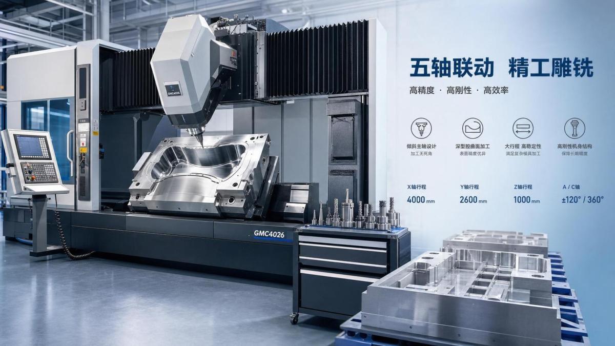
A 5 axis CNC router for molds is used when part geometry cannot be finished efficiently from simple top-down access. Deep cavities, compound curves, undercut regions, and blended transitions all push beyond 3-axis practicality.
In those cases, extra rotary motion is not just a convenience. It helps maintain tool angle, shorten setups, reduce manual repositioning, and improve consistency between roughing, semi-finishing, and finishing stages.
The industrial relevance is broad. Mold programs support thermoformed packaging tools, composite patterns, furniture component molds, trim tooling, and custom fixtures that bridge design data with repeatable production.
From a business view, the machine is often evaluated against two competing demands. One is flexible geometry. The other is predictable throughput without hidden downstream work.
Surface finish starts long before polishing
When buyers compare a 5 axis CNC router for molds, they often ask for spindle power first. That is useful, but finish quality usually depends on a wider stack of machine behavior.
Surface finish is shaped by motion smoothness, servo response, vibration control, thermal stability, interpolation quality, spindle runout, and toolpath execution under load.
If the machine can only hit a surface by using very slow feed rates, the finish may look acceptable during trials yet become expensive in production. Cycle time and quality need to be read together.
The finish-related specifications worth checking
- Spindle runout and bearing quality, because tiny radial error quickly prints onto mold surfaces.
- Control look-ahead and interpolation capability, especially on dense 3D toolpaths.
- Axis acceleration and jerk behavior, since abrupt motion leaves witness marks.
- Machine damping, because chatter ruins both finish and tool life.
- Thermal drift over long runs, particularly on larger molds or extended finishing cycles.
A useful evaluation method is to ask how much hand finishing remains after machining a representative mold material. That result often says more than a generic roughness claim.
Travel is not the same as usable working envelope
Travel numbers on a datasheet can be misleading. For a 5 axis CNC router for molds, the real question is whether the machine keeps full access when the spindle tilts and the workholding grows more complex.
Nominal X, Y, and Z travel may look generous. Yet rotary limits, head geometry, collision zones, fixture height, and tool length can shrink usable capacity far below advertised values.
This issue matters most when mold programs change frequently. A machine that handles today’s part size may struggle once deeper cavities, larger clamp systems, or longer cutters are introduced.
Questions that reveal true travel capacity
For review work, it helps to map the largest planned mold, the deepest cavity, and the longest expected tool into a single interference study before discussing price.
Rigidity is the quiet driver of accuracy and machine life
Rigidity is often treated as a background feature, yet it is central to whether a 5 axis CNC router for molds can stay accurate over years instead of months.
In practice, rigidity means more than a heavy frame. It includes gantry structure, head design, rotary axis stiffness, guideway selection, ballscrew or linear motor behavior, and joint integrity.
Mold finishing exposes weaknesses quickly. Even small deflection changes cutter engagement, leaves blend errors, and forces operators to lower feed or reduce step-over beyond what the program intended.
Where rigidity shows up in daily operation
- Stable corner transitions on sculpted surfaces.
- Lower chatter risk during semi-finishing with longer tools.
- Better dimensional repeatability after tool changes.
- Less compensation drift between day and night shifts.
- Reduced mechanical wear when the machine runs mixed material programs.
This is one reason PWFS often links woodworking automation logic with broader industrial equipment analysis. Across different sectors, the best machines are the ones that hold process stability, not just peak speed.
Material, application, and process route change the right specification
There is no single best 5 axis CNC router for molds. The right configuration depends on mold material, surface expectation, batch rhythm, and how closely CAD, CAM, and shop-floor execution are connected.
For resin boards and softer composites, high spindle quality and smooth kinematics may matter more than extreme cutting force. For aluminum tooling, structural stiffness and thermal control become more important.
Packaging-related mold work often values speed with acceptable finishing effort. Furniture and architectural molds may prioritize complex geometry and flexible one-off programming. Composite patterns usually stress dimensional stability across larger parts.
Typical decision patterns
That is why the buying process should start from part families and process flow, not from a generic machine category alone.
What to verify before detailed vendor comparison
Before moving into commercial negotiation, a practical shortlist for any 5 axis CNC router for molds should be built around proof, not brochure language.
- Request sample cuts in the same material family and with comparable cavity depth.
- Review finish quality after machining and after minimal manual touch-up.
- Check actual cycle time using realistic step-over and feed settings.
- Confirm reachable envelope with fixture, toolholder, and tilt limits included.
- Ask for rigidity evidence through load tests, vibration data, or long-run repeatability records.
- Review control compatibility with the CAM environment already used upstream.
- Look at service response, calibration routines, and spare-part availability.
A strong evaluation matrix connects technical parameters with operational impact. That makes it easier to compare machines that look similar on paper but behave very differently in production.
A better next step than chasing top-line speed
A capable 5 axis CNC router for molds should be judged as a process platform. Surface finish, travel, and rigidity are not separate boxes. They define whether mold quality can be achieved repeatedly and economically.
The most useful next step is to turn current and planned mold families into a structured requirement sheet. Include materials, cavity depths, finish targets, fixture assumptions, cycle expectations, and tolerance risk points.
With that baseline, machine comparison becomes clearer. It also aligns well with the PWFS approach to intelligent equipment assessment: connect design intent, motion physics, and production reality before capital is committed.
Related News
Get weekly intelligence in your inbox.
No noise. No sponsored content. Pure intelligence.
