
CNC Processing of Plywood Panels: How to Prevent Tear-Out During Cutting
A plywood component can come off the CNC router at the correct dimensions and still be unusable because its face veneer has chipped along the cut. On cabinet sides, shelves, and exposed furniture panels, that damage creates extra sanding, compromises edge banding preparation, or turns the part into scrap. To prevent tear-out, start by matching the cutter’s axial cutting direction to the faces you need to protect, then verify cutting depth, panel support, and chip load.
Clean edges in wood panel processing for plywood depend on those conditions working together. A sharp compression bit is often the right choice for through-cutting both faces, but it will still damage the top veneer if the first cutting pass engages only its upcut section. Before changing spindle speed or buying another tool, identify where the damage starts and whether the panel moves during machining.
Read the damaged edge before changing settings
Plywood consists of alternating veneer layers bonded together. The thin outer veneer has limited support at an exposed edge, and cutting forces can lift or split its fibers before the cutting edge severs them. Grain direction changes around a contour, so the same toolpath may leave one edge clean and chip another.
Inspect the top face, bottom face, and exposed core separately. Keep a rejected part beside a clean one, with their sheet orientation marked, so you can distinguish a recurring machining problem from a local panel defect.
A dark, polished edge points toward heat and rubbing rather than veneer lifting alone. Repeated ripples suggest vibration or runout. These symptoms may occur together, but reducing feed indiscriminately can make rubbing worse without resolving the tear-out.
Choose cutter geometry for the surfaces that matter
Upcut spiral bits pull chips upward and generally protect the bottom edge because their axial force draws the lower fibers toward the panel. They can lift the top veneer. They are useful for pockets where chip evacuation matters, provided the top edge is protected by a suitable entry or scoring strategy.
Downcut spiral bits push the upper fibers into the sheet and usually leave a cleaner top edge. Their downward chip flow can pack debris into deep slots, increasing heat and cutting resistance. During through-cutting, the bottom veneer is vulnerable unless it has effective backing.
Compression bits combine an upcut section near the tip with a downcut section above it. With the transition positioned inside the panel thickness, the lower section supports the bottom face while the upper section presses the top fibers inward. This makes compression tooling a strong starting point for two-sided plywood profiling, not a guarantee independent of setup.
Check the tool drawing or manufacturer’s specification for upcut length, cutting length, diameter, flute count, and approved operating limits. “Compression” alone does not establish whether a particular bit suits a thin panel or a shallow first pass.
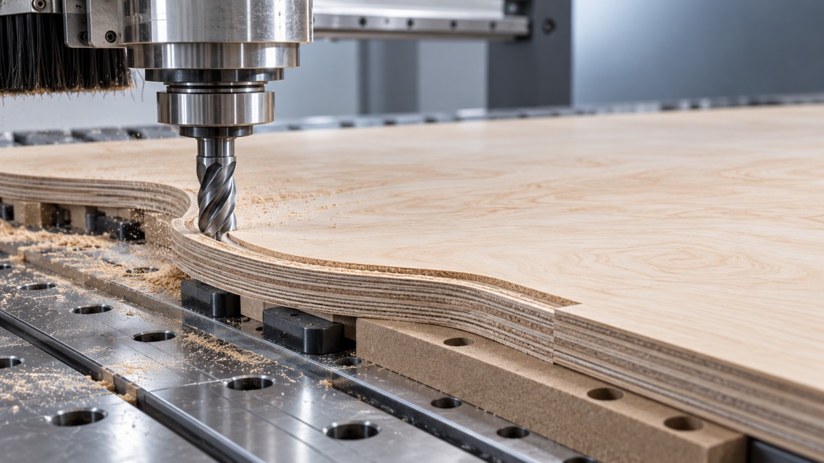
The first-pass depth is a common source of top-face damage
If a compression cutter’s first pass is shallower than its upcut section, the top veneer encounters upward-cutting flutes. The result can look like a defective compression bit even though the tool is working as designed. For compression action at the top surface, the cutting depth must extend beyond the upcut length, with suitable allowance for sheet variation and Z-setting accuracy.
That requirement does not justify taking an excessively deep pass. When the required engagement exceeds the safe cutting load for the machine, tool, or workholding, use a short-upcut compression cutter or a separate top-edge scoring operation. Follow the tooling supplier’s depth and engagement guidance.
At full depth, confirm that the lower face remains within the upcut section. Excessive penetration into the spoilboard can move the compression transition below the panel’s bottom surface, defeating the intended protection of the lower veneer.
Restore support before tuning the cutting program
A plywood sheet that looks flat may still bridge a worn spoilboard or lift near a corner. That gap leaves the bottom veneer unsupported and permits vibration. A vacuum gauge reading alone does not prove that every part of the sheet is held firmly.
- Check spoilboard contact: Surface the board when unevenness prevents consistent contact. Remove chips trapped beneath the sheet.
- Check the vacuum system: Inspect seals, inactive zones, leaks, and filter condition according to the machine instructions. Watch for loss of hold-down as cuts open leakage paths.
- Inspect sheet flatness: Bowed panels may require a different approved holding arrangement rather than relying on vacuum to flatten them.
- Plan small-part retention: Use suitable tabs, an onion skin, or an approved fixture so the component cannot shift during its final contour.
A sacrificial backing board can support the lower veneer, but it must contact the panel closely. Set through-cut depth from measured sheet thickness and the actual machine reference. Unnecessary spoilboard penetration increases wear and may affect compression engagement.
Stop the spindle and follow the machine’s isolation procedure before touching tooling, removing trapped material, or checking fixtures. Never try to steady a moving part by hand.
Set feed and speed as a pair
Feed rate and spindle speed determine the nominal feed per tooth, commonly called chip load:
Chip load = feed rate ÷ (spindle speed × number of cutting flutes).
Use consistent units and start within the tool manufacturer’s range for plywood, cutter diameter, and cutting engagement. There is no universal clean-cut RPM: veneer species, adhesive, tool geometry, slot depth, and machine rigidity all affect the usable range.
Too little chip load can make the edge rub instead of cutting efficiently. Heat, fine dust, resin buildup, and premature dulling may follow. Excessive chip load increases cutting forces and can cause fiber breakout, chatter, or panel movement. A full-width slot also loads the tool differently from a light finishing pass.
Keep a record of actual feed, not just programmed feed. Short segments and tight corners may cause the controller to slow substantially while spindle speed stays constant. Damage concentrated in those areas can indicate a motion or toolpath issue rather than a poor straight-line setting.
Change one variable at a time on an offcut from the same material. Inspect both faces after each cut and watch for rising cutting noise, burning, chip packing, or movement. Do not exceed tool or machine limits to chase a cleaner edge.
Protect the veneer at entry, corners, and final release
Entry damage is easy to mistake for general tear-out. A compression tool plunging or ramping through the finished contour may lift the top fibers before its downcut section engages. Place the entry in waste material where possible, then approach the contour with an appropriate lead-in. Confirm that the cutter is approved for the selected plunge or ramp strategy.
A separate scoring pass with suitable downcut tooling can sever the upper veneer before deeper machining. It must follow the intended edge accurately and reach through the face veneer without adding unnecessary depth. A shallow scoring pass with the upcut tip of a compression bit does not provide the same protection.
Climb cutting often produces a cleaner edge in CNC routing, but it is not automatically preferable on every grain orientation or setup. Compare climb and conventional directions on a representative test contour, using secure workholding. A change of direction may help a troublesome edge while increasing load or reducing stability elsewhere.
For demanding exposed edges, rough slightly away from the final contour and remove the remaining allowance with a finishing pass. Leave enough material for the finishing tool to cut rather than merely rub. A finish pass cannot repair chips that already extend beyond the final edge.
An onion skin keeps a thin layer beneath the part until a final pass, helping preserve vacuum and restrain small components. Its thickness must accommodate panel and spoilboard variation. Inspect the release pass separately: once that skin is removed, the part needs sufficient remaining hold-down to resist lateral movement.
Check tool condition and material quality separately
Plywood adhesives and abrasive inclusions can dull cutting edges. Inspect for chipped carbide, rounded edges, and buildup using the machine’s safe tool-handling procedure. Clean the collet and shank, verify correct insertion, and minimize unnecessary tool overhang. Runout can leave one flute carrying more load than the others.
If a known-good cutter improves the edge under otherwise unchanged conditions, tool wear is a plausible cause. If damage persists at the same locations across different tools, investigate support, toolpath behavior, and panel construction instead of repeatedly replacing cutters.
Core voids and weak glue lines can break away even when both outer veneers are cut cleanly. Separate face tear-out from internal delamination by inspecting the exposed edge. When several sheets show loose plies or open bonds, isolate that material for assessment; machining adjustments cannot restore missing support or failed bonding.
Prove the correction on a representative cut
A straight test slot is not enough to qualify a nested furniture program. Use a test containing an outside contour, a corner, and a small feature, with cuts both along and across the face grain. Include the entry and final-release strategy used in production.
- Measure panel thickness and inspect flatness, veneers, and visible core defects.
- Verify cutter condition, compression geometry, Z reference, and workholding.
- Run the representative cut within approved tooling parameters.
- Inspect the top edge, bottom edge, and core before sanding conceals defects.
- Adjust the suspected cause only, then repeat the same cut for comparison.
Define acceptance around the component’s next operation. An exposed veneer edge may need a stricter standard than an edge that will be trimmed, but edge banding should not be expected to conceal deep chips or loose plies. Record the accepted material, tool, pass depths, feed, spindle speed, and retention method together. Recheck the process when sheet construction, cutter geometry, or part size changes, because those changes can invalidate an otherwise reliable setup.
Related News
Get weekly intelligence in your inbox.
No noise. No sponsored content. Pure intelligence.
