
How Pressure and Feed Settings Affect Edge Banding Quality
A visible glue line or a row of trim marks can appear even when an edge bander is running without alarms. Pressure and feed settings are frequent suspects: they affect how the adhesive wets the mating surfaces, how firmly the band is held against the panel, and how steadily the assembly passes through the trimming stations. Neither setting works in isolation. A pressure change cannot compensate reliably for cold adhesive, a rough panel edge, a slipping feed system or a poorly positioned cutter.
For technical evaluators, the useful question is not simply whether a machine can run faster or apply more force. It is whether the machine can maintain a repeatable bond and an acceptable visible edge across the materials, panel sizes and production conditions it will actually encounter. A sound assessment separates bonding defects from machining marks before changing settings.
What pressure does at the bonding station
In a conventional hot-melt edge banding process, adhesive is applied to the panel edge or the band, depending on the machine configuration. The band meets the panel and passes through pressure rollers while the adhesive is still capable of wetting and joining the surfaces. The rollers must press the band into contact across the intended bond area without disturbing the panel or damaging the visible face.
If effective contact pressure is too low, gaps can remain between the band and the substrate. The resulting bond may be weak in localized areas, and the glue line may look uneven because the adhesive has not spread consistently. Insufficient contact can also result from a misaligned roller, a roller that does not reach the full panel thickness, or a panel that is not held squarely. Increasing a pressure setting will not necessarily correct those mechanical conditions.
Too much pressure presents a different set of risks. Depending on the adhesive, band material and panel condition, it may force adhesive out of the joint, mark a soft band or deflect a thin panel. Excess squeeze-out can make the joint more conspicuous and add cleaning work. A starved-looking joint, however, should not automatically be blamed on high pressure: inadequate adhesive application or poor wetting can produce a similar appearance.
The machine’s displayed pressure is only part of the picture. An air-pressure setting, for example, is not the same thing as a verified contact force at the joint. Cylinder condition, roller geometry, adjustment and the number of rollers sharing the load all affect what reaches the workpiece. When comparing machines, evaluators should ask how pressure is adjusted, how repeatably it is applied and what checks are available for roller alignment and wear.
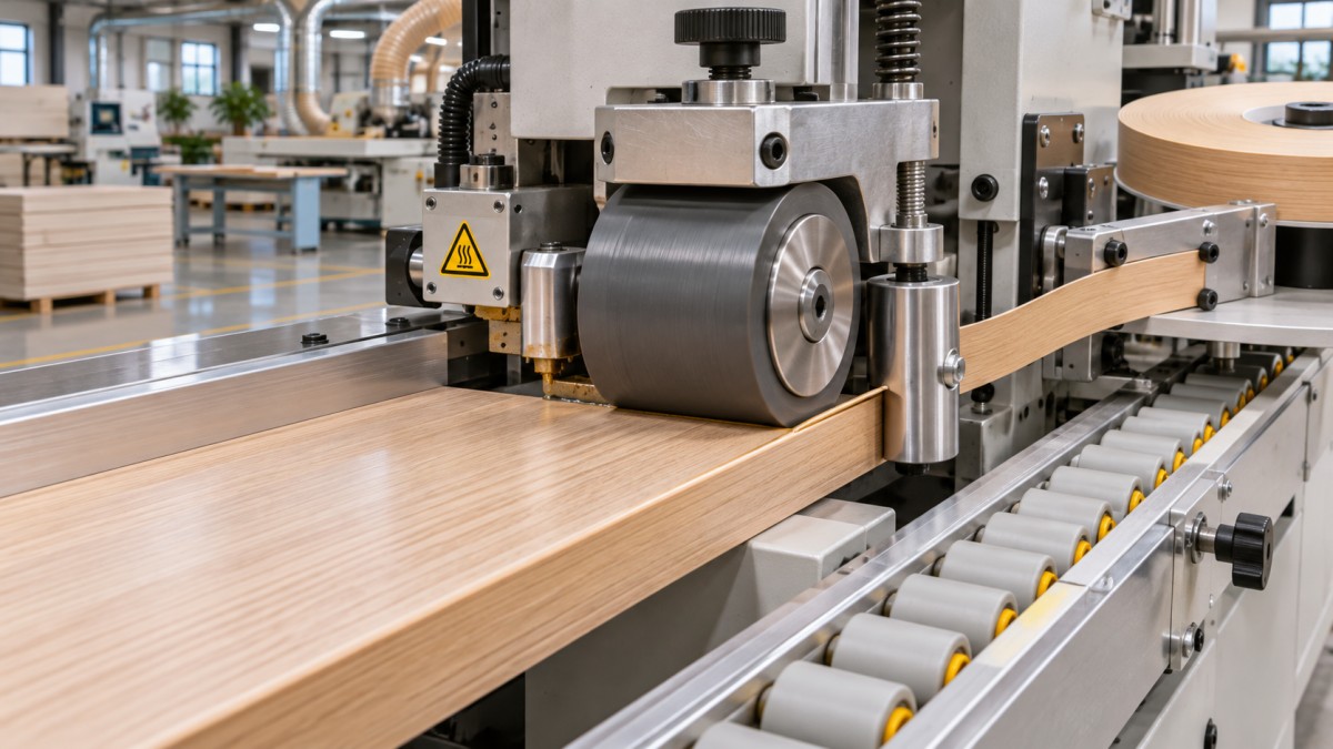
Feed speed changes the bonding window
Feed speed determines how quickly the panel moves from adhesive application into the pressure zone and onward to trimming. At a higher speed, there is generally less elapsed time for heat to transfer or dissipate over a given distance between stations. The adhesive may reach the rollers in a different condition than it does at a slower speed. Whether that helps or harms the bond depends on the adhesive, application temperature, coating amount, ambient conditions and machine layout.
A slower feed is not automatically safer. It may give an exposed adhesive film more time to cool before pressure is applied, particularly if the distance between application and contact is substantial. It can also change the amount of adhesive deposited per unit length if the application system does not compensate appropriately for speed. Conversely, increasing speed can expose limitations in adhesive delivery, heating capacity or workpiece control.
Feed speed also affects the trimming process. If cutter rotation remains unchanged while feed speed rises, each cutting edge generally removes a larger length of material per pass. Depending on cutter geometry and other conditions, the resulting machining pattern may become more visible. At the same time, a feed system that allows the panel to hesitate, skew or vibrate can create irregular marks that are not explained by nominal speed alone.
For evaluation purposes, record the actual operating speed as well as the controller setting. Compare it with the adhesive supplier’s processing instructions and the machine maker’s permitted operating range. A speed demonstrated on a short, stable sample may not represent performance on long, narrow or flexible production parts.
Reading glue lines without guessing at the cause
A glue line is evidence of what happened at the interface, not a diagnosis by itself. Its color, width and continuity should be examined alongside the panel edge, band and adhesive residue. A dark or prominent line may reflect excess adhesive, contamination, a poor color match or an uneven interface. A light gap may indicate incomplete contact, but it can also arise from an irregularly machined substrate.
Start with the panel edge before adjusting the pressure rollers. Pre-milling or other edge preparation should leave a consistent surface without loose fibers, chips or large variations in squareness. A roller cannot make a warped panel or a hollow edge flat along its full length. Likewise, a band with inconsistent thickness or curvature can respond differently from one reel to another, even with unchanged machine settings.
Next, inspect adhesive application. An intermittent or uneven coating may point to the application system rather than the pressure station. Check the adhesive type, condition and operating temperature against its supplier’s instructions, and consider whether the panel and band have been stored in conditions that could affect the process. Avoid treating a higher temperature as a universal cure: unsuitable heat can damage material or degrade adhesive, depending on the formulation and exposure.
A practical inspection includes the beginning, middle and end of the part, with attention to both faces. A defect concentrated near an end may call for a different investigation from one repeated over the entire edge. Where bond strength matters, agree on a suitable test with the adhesive supplier or the customer; a visual check alone cannot establish joint performance. The location of adhesive after a controlled destructive check can provide clues about where separation occurred, but interpretation depends on the materials and test method.
Distinguishing trim marks from bonding defects
Trim marks occur after the band has been applied, when cutters remove overhang or shape the edge. They may appear as repeated lines, chatter, steps, local tear-out or a change in the visible profile. Some originate in the cutting process; others begin upstream when the panel or band is not consistently positioned. A poorly bonded band can move during trimming, while a sound bond can still be damaged by a blunt cutter.
Inspect the workpiece at several points along the machine if the layout permits. If a mark is visible before the trim station, changing the trim cutter alone is unlikely to remove its cause. If the band is clean before trimming but marked afterward, investigate the trimming unit, its guides and the way the panel is fed through it.
- Regular cutter pattern: Consider feed speed in relation to cutter rotation, cutter condition and the number and geometry of cutting edges. Confirm that rotation and feed settings suit the tool and machine.
- Irregular chatter or waviness: Check workpiece support, feed continuity, hold-down adjustment and the condition of bearings and guides. Vibration can originate in the workpiece or the machine.
- Marks on one face or a changing profile: Examine panel thickness variation, squareness, guide alignment and the reference surfaces used by the trimming unit.
- Tear-out or smearing: Consider band material, tool sharpness, cutting direction and adhesive condition. A setting that works on one edge material may not transfer directly to another.
Pressure and feed can contribute indirectly. Excessive hold-down pressure may deflect a panel, while insufficient restraint may allow it to move. These are distinct from the pressure rollers at the bonding station and should be identified separately in setup records. Treating every pressure adjustment as the same control obscures the mechanism behind the defect.
A controlled way to isolate pressure and speed
Changing pressure, speed, temperature and cutter settings at once may produce a better-looking sample, but it leaves no reliable explanation for the improvement. It also makes the setting difficult to reproduce when material or operators change. A controlled trial begins with a known material combination and a machine that has been checked for obvious mechanical faults.
- Document the starting condition. Record panel construction and thickness, band material and thickness, adhesive, temperature settings, feed speed, relevant pressure settings and the stations in use. Identify the surface on which each defect appears.
- Establish a baseline. Process representative parts using the machine and material suppliers’ recommended setup ranges. Inspect the joint and trimmed edge at consistent locations and under consistent lighting.
- Change one setting at a time. Adjust bonding pressure in small, documented steps within the permitted range while holding speed and the other relevant settings constant. Return to the baseline before evaluating a different variable.
- Test feed speed separately. Compare suitable speeds while monitoring adhesive application and bond appearance. If the application system changes its output with speed, record that behavior rather than assuming the adhesive film is constant.
- Repeat on representative parts. Include the panel sizes and edge materials that matter to production. Check whether the result holds after the equipment has reached its normal operating condition and across a useful run length.
Photographs taken at the same angle and lighting can help compare visible glue lines and trim patterns, but they should be supported by physical inspection. Record rejected samples as well as acceptable ones. A setting that produces an attractive edge only within a narrow adjustment range may be less useful in production than one that gives a stable result across ordinary material variation.
When symptoms persist, the edge banding troubleshooting guide provides a related reference for organizing machine checks alongside the observations from the trial. The important distinction is between a symptom, such as a visible line, and a verified cause, such as inconsistent adhesive delivery or a roller that is not contacting the workpiece evenly.
What to require in a machine evaluation
A technical demonstration should reflect the buyer’s intended work rather than rely solely on the supplier’s preferred sample. Provide representative panels and edge bands, including parts whose dimensions make feeding or support difficult. Agree in advance on the adhesive, visible-edge criteria, inspection locations and any bond test. If the intended operation includes different materials or frequent changeovers, include those conditions in the assessment.
Ask how the operator sets and verifies feed speed, bonding pressure, hold-down pressure and trim-unit position. Useful documentation identifies the control associated with each function, the permitted adjustment range and the maintenance checks needed to preserve repeatability. A numerical setting is of limited value if there is no clear way to relate it to the workpiece or restore it after a changeover.
Compare the cost of different operating windows as well as the appearance of a single part. A slower setting may reduce visible cutter marks but restrict throughput; a faster setting may require sharper tooling, more stable workpiece support or different adhesive processing conditions. Rework from squeeze-out, rejected panels and time spent resetting stations should be considered against the expected production mix, without assuming that one speed or pressure suits every job.
The most useful acceptance result is a documented combination of material, adhesive, speed and station settings that produces a repeatable edge under agreed conditions. If the acceptable result disappears when the panel size, band material or operating temperature changes, that limitation belongs in the evaluation record rather than being hidden by the best sample.
Related News
Get weekly intelligence in your inbox.
No noise. No sponsored content. Pure intelligence.
