
Mapping Cutting, Grooving and Labeling Workflows for Cabinet Nesting
Cabinet nesting is often evaluated as a cutting process, yet cutting quality is only one part of whether a production cell will support reliable downstream assembly. A nested sheet may leave the router with accurate outer profiles, but production can still slow down if groove locations are unclear, labels do not match parts, or operators must manually interpret panels before edge banding and drilling. For technical evaluators, the useful question is not simply whether a router can machine cabinet components. It is whether the complete workflow keeps panel identity, machining intent, and material flow aligned from job release to packing.
A practical workflow map connects three outputs from the same design data: cut geometry, groove or pocket instructions, and labels that identify each component. When those outputs are generated separately or checked only after machining, small data mismatches can turn into missing backs, incorrectly oriented shelves, duplicate parts, or panels routed on the wrong face. The risk grows in mixed production, where cabinet dimensions, hardware choices, finishes, and grain direction vary from order to order.
Start with the part record, not the router program
Every cabinet component needs a usable identity before it reaches the machine. That identity should travel through the workflow as a part record rather than a handwritten note. At minimum, the record normally includes job number, cabinet or room reference, part name, finished dimensions, material specification, quantity, grain direction, machining face, edge-banding requirements, and assembly orientation. The record may also need hardware-related information such as hinge position, connector pattern, or drawer-slide reference.
In a nesting environment, the CAM system usually converts these records into sheet layouts. The router program determines how parts are cut from a board, while nesting optimization determines sheet utilization and tool movement. Neither function should silently override manufacturing rules. For example, an optimizer may achieve a tighter layout by rotating a panel, but that result is unsuitable when decorative grain, laminate direction, or structural orientation must be preserved. Technical reviews should establish which rules are fixed, which may be relaxed, and who has authority to approve an exception.
The most stable setup uses one controlled source for dimensions and part attributes. Design revisions should flow into the production data through a documented release process. Operators need a clear method for distinguishing an active revision from a superseded one, particularly when a replacement part must be made after the original sheet has already been processed.
Map the machining sequence around material behavior
Cutting, grooving, and labeling are related, but they do not always occur in the same order or at the same station. Their order depends on board construction, surface sensitivity, available equipment, and the level of traceability required on the shop floor. The workflow should be mapped from material receipt through assembly rather than only from CAD export to router cycle start.
For panel processing, a typical route includes material verification, sheet loading, reference registration, nested cutting, internal machining, part identification, sorting, edge treatment, secondary drilling where required, assembly, and packing. A cabinet shop may combine several of these stages, but the handoffs still exist. Each handoff is a possible point of loss: parts can be mixed, labels can detach, or an uncut feature can be discovered only when assembly has begun.
Toolpath order affects both surface quality and part stability. Internal pockets, hinge recesses, grooves, and drilling operations are frequently completed while the sheet remains well supported on the vacuum table. Contour cutting is commonly left until later so smaller components do not shift before their internal features are complete. The appropriate sequence varies with vacuum zoning, spoilboard condition, panel size, small-part geometry, and the use of tabs, onion-skin strategies, or other retention methods.
Routing grooves before final profiling can be helpful where the groove must be accurately located from the sheet datum. Still, the evaluator should check whether groove depth, cutter selection, and feed conditions are appropriate for the panel core. A deep groove in particleboard may weaken a narrow rail; a dull tool may tear a melamine surface at groove entry; and compressed-board dust can reduce vacuum holding if extraction is inadequate. The objective is not to prescribe one universal machining order, but to verify that the selected order addresses the material and part geometry being processed.
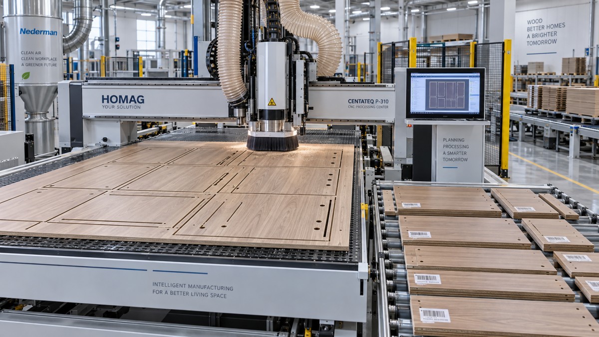
Grooving requires clearer rules than “machine when needed”
Grooves serve different cabinet functions and should not be treated as a single generic operation. Back-panel grooves, shelf dadoes, door-panel details, cable channels, and decorative reveals each have different tolerance and face-reference implications. A back groove may need consistent setback from a finished edge. A shelf dado may depend on actual shelf thickness and the desired assembly fit. A decorative groove may be visually sensitive even when its dimensional tolerance is less restrictive.
Technical documentation should define the reference face and reference edges for each operation. This becomes particularly important with coated panels, two-sided finishes, mirrored cabinet parts, and panels that can be machined from either side. “Top” and “bottom” are often insufficient instructions. The work order should indicate the intended visible face, machining face, and orientation at assembly.
Groove quality should be assessed in the condition in which the part will be assembled. A measurement taken immediately after routing may confirm geometry but not reveal chip-out along a visible edge. Conversely, a minor internal edge defect may have no functional consequence if it is concealed and does not affect fit. Inspection criteria need to distinguish cosmetic surfaces from hidden structural features, rather than applying a single visual standard to every cut.
Labels are a production control, not a finishing detail
Part labels make nested manufacturing workable when multiple cabinets are cut from the same sheet. They allow operators to sort components by job, cabinet, and assembly sequence without relying on memory or sheet position. Yet labels only add value when their contents, print timing, placement, and durability have been designed around the actual route.
A useful cabinet label often includes a human-readable part description and a machine-readable identifier. The code can support scanning at edge banding, drilling, kitting, or packing, while the readable text helps when scanners are unavailable or a label is damaged. The label should carry enough context for a person to avoid basic errors: job reference, cabinet reference, part identity, quantity, material or finish where needed, and an orientation indicator. Including every available data field can make labels crowded and difficult to read under production conditions.
Placement deserves the same level of planning as the code itself. A label placed on a visible finished face may create a cleaning issue or leave adhesive residue. A label on an edge-banded side may be removed during trimming. A label on a narrow offcut-prone area can disappear before sorting. Many operations place labels on a non-visible face or in a location protected from later machining, but the correct location depends on the process route and whether the panel will be flipped.
Printing before machining creates early traceability but exposes labels to dust, vibration, and potential damage. Printing after routing provides a better match to actual completed parts, but it requires a reliable method to keep components associated with their digital records while they leave the nest. Some cells use print-and-apply equipment integrated with the router discharge; others rely on an operator-led print sequence. Either approach should be tested with real sheet mixes, small components, rework parts, and high-volume batches rather than with a simple demonstration program.
Evaluating a cabinet nesting cell as a connected configuration
Machine selection should begin with the cabinet mix and workflow constraints, not with a broad claim about routing capacity. Evaluators should establish the largest and smallest parts expected, panel thickness range, coated versus raw board mix, daily material changes, expected frequency of one-off work, groove types, and downstream equipment. A cell producing repeatable flat-pack components may prioritize sheet throughput and barcode continuity. A shop handling custom interiors may place greater weight on fast job changeover, clear operator verification, and reliable rework handling.
Where a router is being assessed as part of a broader nesting workflow, the ZD1325 cabinet nesting configuration can be reviewed as a reference point for matching a CNC nesting machine to the required cutting and panel-processing route. The key evaluation task is to confirm the configuration against the actual process map: sheet format, tool requirements, vacuum strategy, dust extraction interface, label handoff, software compatibility, and the type of groove work expected. A machine specification alone cannot establish whether the surrounding data and handling steps will preserve part identity.
Tool capacity should be considered in relation to program complexity. A process that uses separate tools for profiling, grooving, drilling, and finish-sensitive operations may require more tool management than a basic cut-only program. Tool changes add cycle time, but reducing tool variety indiscriminately can compromise groove finish or dimensional consistency. The appropriate balance depends on the proportion of parts requiring multiple operations and the practical consequences of manual tool intervention.
Vacuum performance is another system issue. A high-nesting yield can leave small or narrow components with limited holding area. If the layout contains many such parts, machine availability may be affected by manual intervention, re-cuts, or conservative feed rates. Evaluators should request representative nesting simulations or trial programs that include the difficult shapes found in the actual cabinet range, not just large rectangular panels.
Use acceptance tests that follow the part beyond the router
A meaningful acceptance plan should test more than spindle movement and dimensional output from a single sample. It should use a defined material set, released cabinet data, typical grooves, small parts, finished-face panels, and labels that will pass through the intended downstream process. The goal is to observe the chain of custody from sheet loading to a correctly identified component ready for the next operation.
- Verify that the correct revision, material code, grain rule, and machining face reach the CAM output.
- Check first-off parts for overall dimensions, groove position and depth, internal features, edge condition, and retained part stability.
- Confirm that every separated component receives or retains the correct label, including mirrored and repeated parts.
- Follow selected parts through sorting and edge treatment to see whether the label remains readable and correctly oriented.
- Test a controlled rework scenario: identify a missing part, regenerate it from the approved record, and confirm that it does not create a revision conflict.
These checks reveal issues that are easy to miss during a short machine trial. A cell may cut accurately while still producing avoidable disruption if labels are poorly placed, if operators cannot distinguish faces, or if rework depends on informal notes. The strongest cabinet nesting workflow is one in which cutting geometry, groove instructions, and label data are generated from the same controlled part definition and remain understandable at every handoff. That alignment is what turns a router from an isolated cutting asset into a dependable production system.
Related News
Get weekly intelligence in your inbox.
No noise. No sponsored content. Pure intelligence.
