
How to Specify a CNC Door Machining Cell for Solid Wood and MDF Production
A CNC door machining cell should be specified from the finished door backward, not from the machine brochure forward. The right configuration depends on whether the factory is machining one-piece MDF doors, five-piece solid-wood doors, veneered components, or a mixed catalog with frequent size and hardware changes. Spindle power, table length, and axis count matter, but they do not define whether a cell will hold hinge locations, protect visible surfaces, manage wood movement, and maintain output when the order mix changes.
For buyers assessing woodworking CNC machines for doors, the practical question is: which machine architecture will produce the intended door designs at the required quality level with the least handling, rework, and programming friction? That question should be answered before comparing brands or optional equipment.
Start with the door family, not the material label
“Solid wood and MDF” is too broad to be a useful machine specification. An MDF shaker door with routed panel detail behaves very differently from a solid-wood stile-and-rail door. The first may be efficiently cut from a flat blank in a nesting workflow. The second requires accurate machining of individual rails, stiles, panels, and often end-grain joints. A cell intended for both needs a more deliberate process design than one dedicated to either product.
Build the specification around representative door families. Include the largest and smallest panel sizes, the thickest and thinnest workpieces, common edge profiles, routed patterns, hinge cup positions, lock or handle drilling, pocketing, cutouts, and any operations on both faces. Include outliers as well: arched top doors, narrow fillers, louvered elements, deep grooves, raised panels, and doors requiring angled or compound machining.
This exercise reveals whether the operation is primarily a panel-processing task, a component-machining task, or a hybrid. It also exposes a common selection error: buying a high-output nesting router for a product mix that contains too many edge, end, and multi-face operations. The router may cut the outline quickly, but operators can lose that time again through secondary setups.
Choose between nesting and pod-and-rail based on operation access
A nesting table holds sheet goods with vacuum while the machine cuts, drills, and pockets from above. It is often a strong fit for MDF door fronts, cabinet-style panels, and work released from a design-to-production system as nested sheets. It reduces manual sizing and can consolidate several face operations in one program. Its limitations emerge when parts are small, narrow, heavily machined on the edge, or when machining must extend close to the holding surface. Vacuum performance also depends on the part geometry, gasketing strategy, spoilboard condition, and the available sealing area.
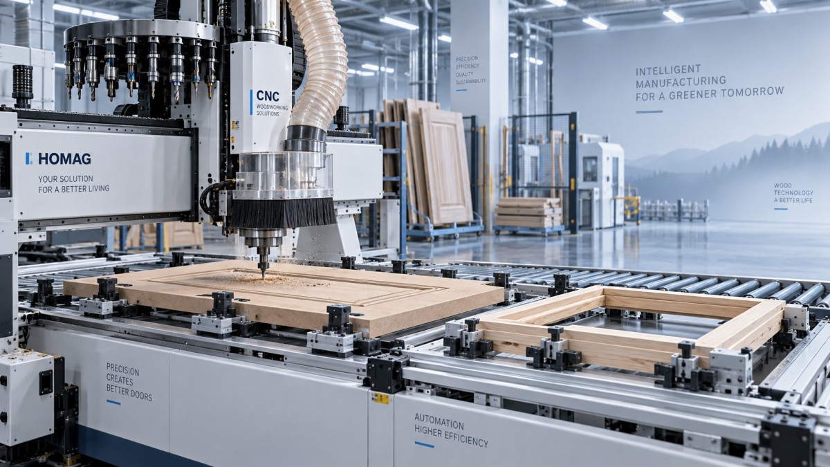
Pod-and-rail systems use movable vacuum pods or mechanical supports to hold a panel above the machine bed. This improves access to edges and allows more complete machining of a door or component in one setup. It is useful for hinge bores, edge drilling, lock preparation, and shaped work where through-cutting on a spoilboard is undesirable. The tradeoff is setup complexity. A flexible table is only productive when pod placement, clamping rules, and collision checks are integrated into the programming workflow.
For solid wood, component-based fixturing may be more important than either broad table format. Stiles and rails need secure support while cutters enter end grain or form joints. A long workpiece can vibrate even when it appears clamped. That vibration affects joint quality, profile consistency, and tool life. The machine specification should therefore address fixture stiffness, support locations, reference stops, and the ability to process multiple matching parts without resetting the datum.
Do not assume a five-axis head is automatically necessary. Five-axis capability is justified when door designs require angled holes, sculpted surfaces, compound profiles, or tool access that cannot be achieved efficiently with standard vertical and horizontal aggregates. For conventional slab doors, shaker routing, hinge boring, and square-edged components, a well-configured three-axis or four-axis machine can be simpler to program and easier to keep productive. Axis count should follow geometry, not prestige.
Material behavior changes the cell requirements
MDF is dimensionally consistent compared with solid wood, but its machined edge quality is sensitive to cutter condition, feed strategy, compression of the board surface, and chip evacuation. Painted MDF doors often make edge defects visible after finishing. The CNC cell should support tooling that produces clean routed edges and should leave enough process control for finish sanding without changing the intended profile. Small voids, fuzzy fibers, chipped edges, and inconsistent tool marks are not always machine problems; they can originate in board quality, worn tooling, poor extraction, or a toolpath that is too aggressive for the detail.
Solid wood introduces different risks. Moisture variation, grain direction, internal stress, and natural movement can affect flatness and dimensions before and after machining. A machine can repeatedly cut to program and still produce assembly problems if parts enter the cell unstable. Technical specifications should define acceptable incoming stock condition, machining reference faces, and how cupped or twisted blanks will be handled. A CNC does not correct poorly conditioned stock.
Grain direction also affects cutter selection and cutting direction. Profile tear-out is more likely on difficult grain, especially around transitions and on routed decorative details. The best result may require climb or conventional cutting choices at different stages, a finishing pass, or tooling designed for the material and coating system. Evaluators should ask suppliers to demonstrate the actual edge profile on representative solid wood, not merely a generic pocketing sample.
Specify accuracy as an assembly requirement
Door production needs more than a statement of nominal positioning accuracy. The relevant issue is whether features relate correctly to one another after the workpiece has been loaded, machined, unloaded, sanded, finished, and assembled. Hinge cups must align with the door edge and corresponding cabinet hardware. Rail-and-stile joints must close without forcing. Decorative routed details must remain centered after trimming. Paired doors must look consistent when installed.
Define tolerances by feature and by functional relationship. For example, distinguish between overall blank size, hole-to-edge position, hinge-to-hinge spacing, joint location, depth-controlled pockets, and profile consistency. Require the supplier to explain the workholding reference used for each critical feature. A capable servo system cannot compensate for a part that shifts under vacuum or is referenced from an inconsistent edge.
Repeatability across a normal production shift matters more than a single favorable sample. A useful acceptance approach includes the full operating sequence: loading, tool changes, drilling, routing, offloading, and repeated runs of the same program. It should also include both small and large doors, because holding behavior and machine dynamics change with part size.
Tooling, drilling, and aggregates must match the design library
The spindle is only one part of the cutting system. Door machining often combines profile tools, compression cutters, drills, hinge cup borers, grooving tools, saw blades, and horizontal drilling units. A machine with an automatic tool changer can still become inefficient if the magazine lacks capacity for the tools needed across a typical batch, or if the tool management system does not track tool identity and wear.
List every operation performed on a representative order batch, then identify the required tool, orientation, depth, and approach direction. This clarifies whether the cell needs a vertical drilling block, horizontal drilling aggregate, angle head, saw aggregate, or simply a robust set of standard tools. It also prevents over-specifying expensive aggregates for operations that occur rarely and can be handled more sensibly elsewhere.
Tooling strategy should include controlled tool replacement rather than relying only on visible deterioration. A dull cutter raises cutting forces, increases heat, degrades edge finish, and can pull fibers from MDF or tear solid-wood grain. The cell software should make it practical to manage tool records, offsets, and replacements without inviting operators to make manual corrections that disrupt dimensional control.
Automation only pays when material flow is stable
Automatic loading, unloading, labeling, return conveyors, and robotic handling can reduce handling time and improve traceability. They are most valuable when blank sizes, workpiece orientation, buffers, and downstream operations are stable enough to support continuous flow. In a highly variable custom door shop, a flexible manual loading arrangement may outperform a rigid automated layout if frequent exceptions interrupt the system.
Evaluate automation as part of the whole cell. Consider where unfinished blanks wait, how door faces are protected, how offcuts are removed, how labels follow parts into sanding and finishing, and what happens when one machine stops. A fast CNC with inadequate staging space merely moves congestion upstream or downstream.
For made-to-order production, the software connection may have greater value than aggressive physical automation. The cell should receive reliable dimensions, hinge rules, hardware references, grain direction, machining faces, and revision status from the production system. A parametric program structure reduces repetitive programming, but only when design rules are controlled. A wrong handedness flag or outdated hardware pattern can create an entire batch of unusable doors quickly.
Dust extraction is part of machining quality
Door machining creates large volumes of chips and fine dust, especially during deep routing and MDF processing. Extraction capacity, hood design, duct routing, and machine cleaning access affect more than housekeeping. Poor chip removal can mark a finished face, recut chips along an edge, reduce cooling around the cutter, interfere with vacuum sealing, and obscure sensors or reference surfaces.
Specify extraction connections for the actual set of tools and aggregates, including operations that generate chips in different directions. Assess whether the extraction hood follows the tool effectively during deep pockets and edge machining. Also consider cleanup time between materials. Dust from MDF and chips from solid wood behave differently in a cell, and mixed production can make manual cleaning a recurring productivity loss.
Use the supplier demonstration to test the cell, not the brochure
A meaningful demonstration should use the factory’s own drawings, materials, hardware patterns, and surface-quality expectations. Include an MDF routed door, a solid-wood component or assembled-door element, a part with hinge and edge drilling, and a design that exercises the most demanding tool access. Observe setup time, fixture changes, tool changes, program loading, part unloading, and how the operator recovers from a normal interruption.
Ask practical questions: Which operations require repositioning? What prevents a narrow part from moving? How are tool collisions avoided after a fixture change? Which dimensions are referenced from the finished visible edge? Can the program distinguish left-hand from right-hand doors automatically? How are remakes identified and rerun without losing their production identity?
The supplier’s answers should be visible in the proposed process, not just described as optional capability. A feature that needs specialist intervention or extensive manual workarounds should not be counted as effective production capacity.
A specification sequence that avoids expensive mismatches
- Define the door families and the expected mix of MDF, solid wood, and hybrid construction.
- Map every machining operation by face, edge, end, tool direction, and required datum.
- Identify the workholding method for each difficult part, including narrow, shaped, or unstable components.
- Set functional tolerances for joinery, hardware, and visible routed details.
- Specify tooling, drilling, and aggregate needs from the actual operation list.
- Design the material flow from blank preparation through machining, sanding, finishing, and assembly.
- Test the proposed woodworking CNC cell using representative files and production materials before final approval.
PWFS tracks CNC woodworking equipment in the wider context of digitally connected furniture production, where machining quality depends on the relationship between design data, tooling, material handling, and finishing readiness. That perspective is useful when a door cell must support customization without turning every design variation into a manual setup problem.
The strongest specification is not the one with the longest option list. It is the one that makes the intended doors repeatably, protects the visible surfaces, supports the required product variation, and leaves a workable path for the next increase in volume or complexity.
Related News
Get weekly intelligence in your inbox.
No noise. No sponsored content. Pure intelligence.
